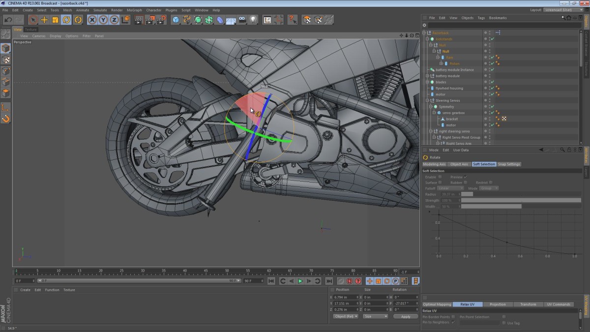
In this video we cover the modeling of the brackets that connect the steering servo gearboxes to the frame. While modeling the brackets, we get to use the Bridge tool to patch up geometry and focus on the benefits of using quads instead of triangles.
We also take a look at the kickstand placement taking issues such as ground clearance and style into account.
Covered in this video:
- Taking a look at the rod used to stiffen the steering brackets on the fork tubes.
- Creating the basic geometry for the bracket. We start with a cube and then re-shape it from there.
- Use of the Bridge tool to clean up extruded geometry.
- Removing some triangles and focusing on quads instead.
- Discussion of the kickstands and what then need to accomplish.
- Using an Array object to place multiple spikes at the base of each kickstand plate. We also use this time to discuss the practical uses of these hydraulic/pneumatic kickstands.
- Placement of the kickstands (taking issues like ground clearance into account).

Juan Carlos Vargas
August 9, 2013 — 5:01 pm
Thanks for sharing your time and wisdom, you are a great artist!