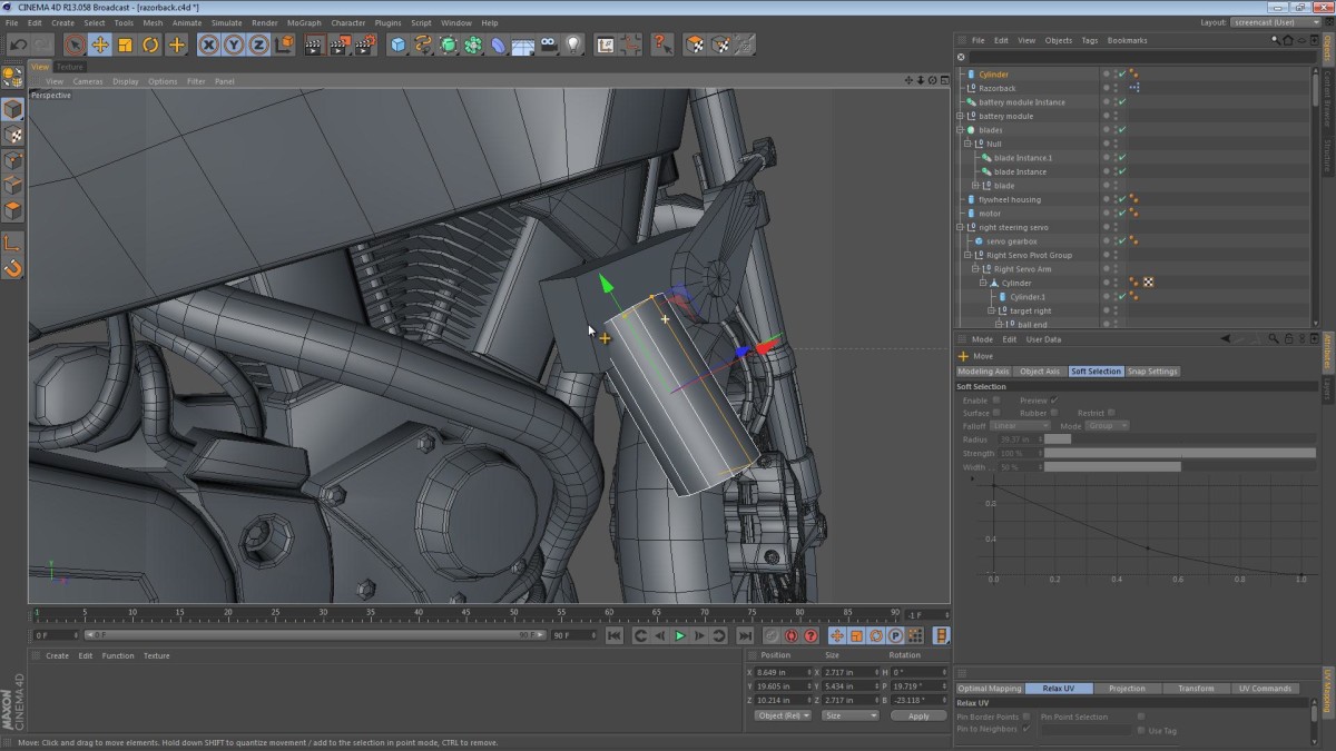
In this video we look more closely at the steering mechanism linkages. We start out by creating a few ball joints and linkages for the steering. We then work on the rigging of the linkages via some Xpresso and the Range Mapper node.
Covered in this video:
- Creating some instanced geometry for the push rod ball joints (linkages) that connect the servo motors to the fork tubes.
- Modeling the ends of the linkages where the ball and socket mechanism exists.
- Adjusting the Phong smoothing tag and creating some low-poly geometry for the aforementioned parts.
- Using a Target tag expression with an up vector to ensure that the push rods behave in a believable manner.
- Using an Xpresso Range Mapper to adjust the travel of the push rods in a non linear fashion (In a very ad-hoc way).
- District 9 & Firefall as inspiration for geometry at arbitrary angles.

stchristoph2000
August 28, 2012 — 11:40 pm
Man you videos are great. I’m learning so much about modeling just looking at you doing it.
Jamie Hamel-Smith
August 29, 2012 — 2:43 am
I’m glad you like them. Thanks for letting me know, it makes all the difference!