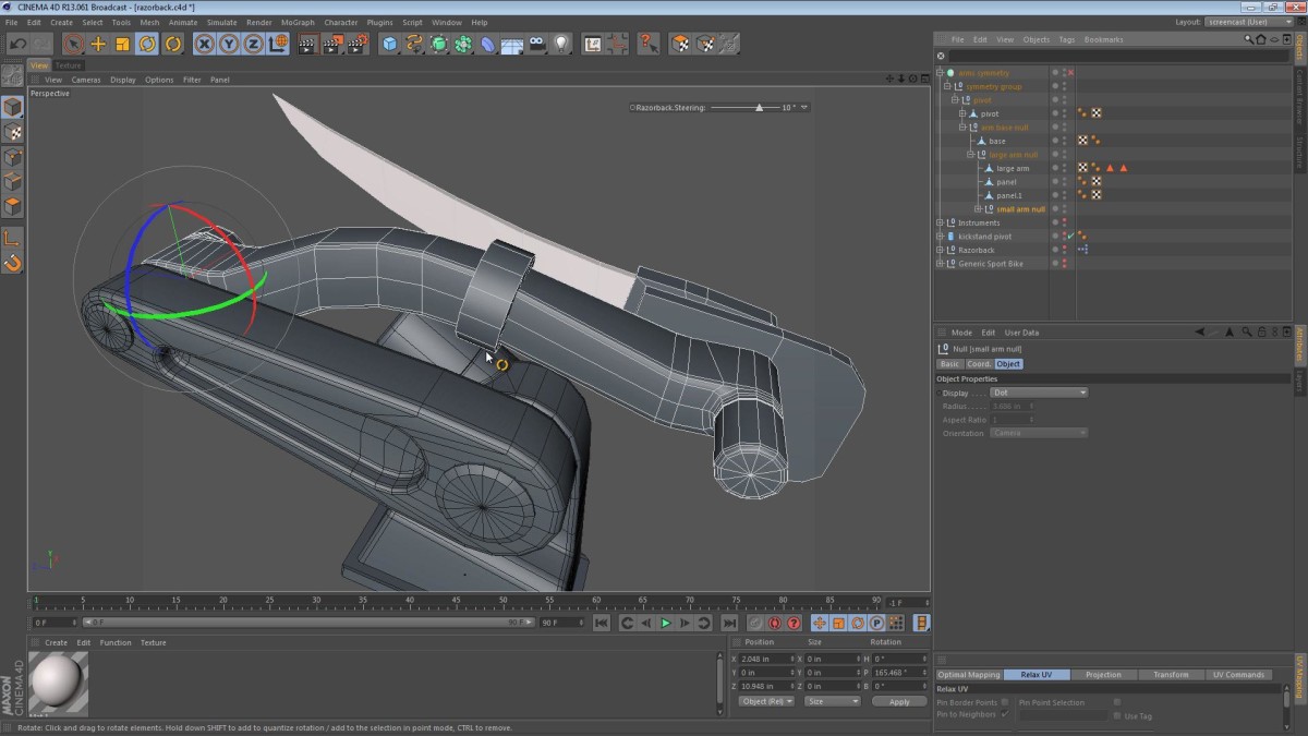
In this part of the Razorback series, we split the upper arm into two pieces. Earlier on in the series I wanted to keep the robotic arms as simple as possible, and while doing so, I unintentionally hampered the range of motion. The following video follows me as I try to correct this situation. The result is actually better looking in my opinion.
Tag: long video
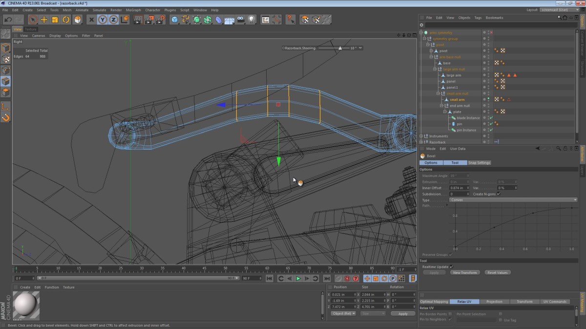
In this part of the Razorback series, we are going to revisit the Pneumatic kickstands. First, we take a second look at the upper robotic arm and make some pretty dramatic tweaks.
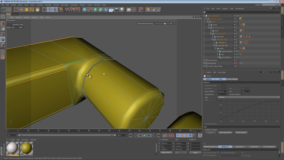
In this installment of the Razorback screencast, we kick things off by reconstructing the upper robotic arm of the machine. There’s a bit of modeling, and some new techniques in store for you.
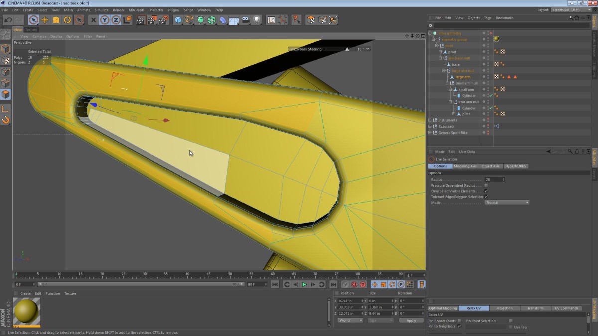
In this part of the series, we continue refining one of the robotic arms, in an effort to make the Razorback’s arms more polished and complete.
Most of the video is spent cleaning up geometry and beveling edges to create smooth transitions.
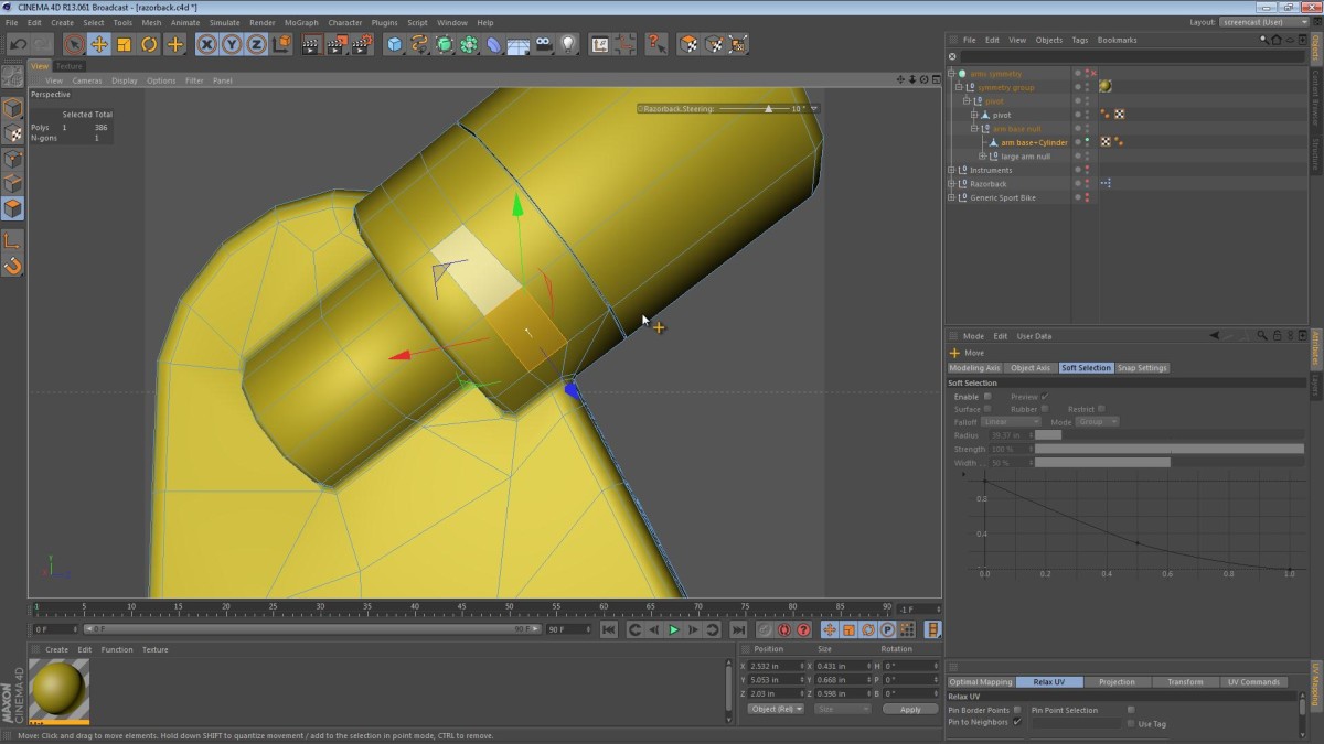
In this part of the video series, we start to give some attention to areas of the model that are still very primitive. I kick things off by refining, smoothing and merging the base of the robotic arms. The base part of the arm has a motor mount fused to the housing as if it were cast from a single mold.
We start by merging the objects, giving it a yellow color and running through some Boolean techniques that may sound familiar if you saw my recent videos on Booleans in Cinema 4D.
I realize that at this stage of the modeling process, I may be making up words like: Boolean-ing and Boolean-ed… I’m OK with that. If we can Google something, then I can consider something Booleaned.
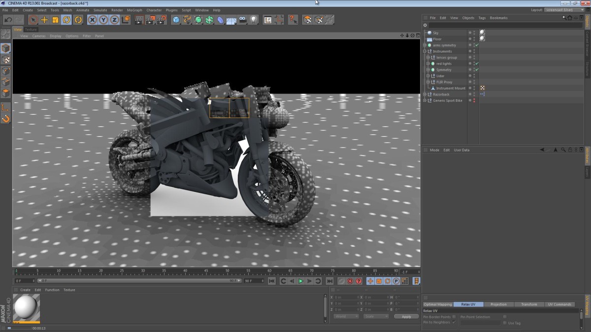
I don’t practice using the MoGraph module enough, and this video proves it.
We start this video on a critical note as I realize that I’m still not happy with the instrumentation cluster on the front of the machine.
At the end of the video, there’s a test render with some simple Global Illumination.
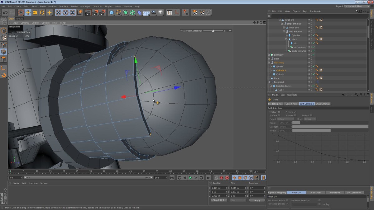
In part 12 of the Razorback series, we take a look at the blade disposal system and the instrumentation array. The instruments are the Razorback’s eyes and ears. This array of optics and other sensors will allow the machine to move through the environment.
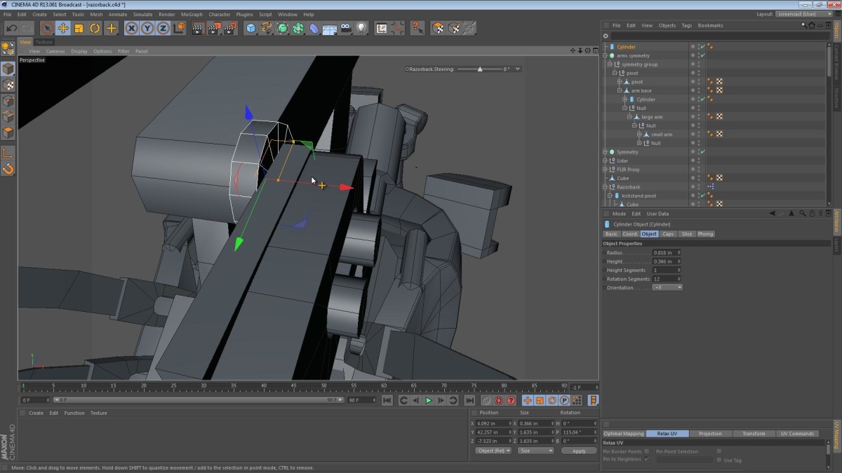
In part 11 of the Razorback series, we start off by looking at the blades and the blade mounting system.
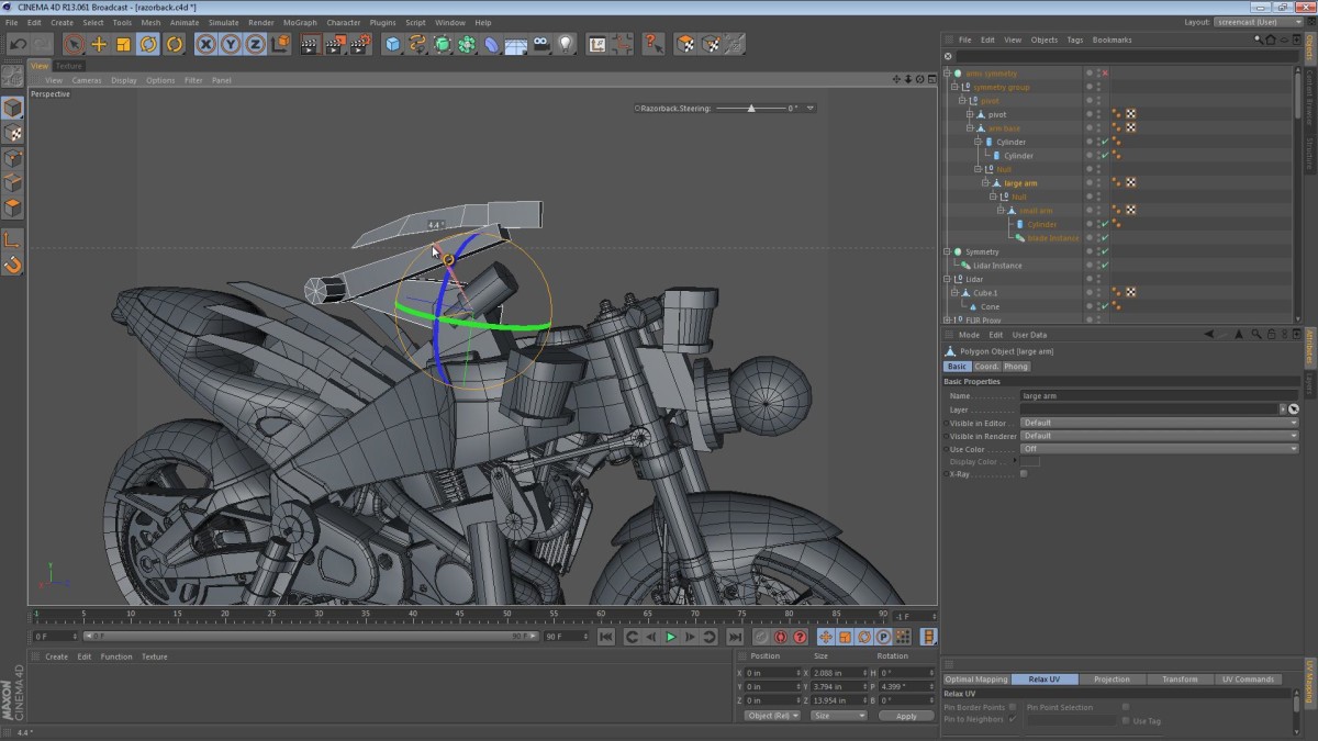
In this part, we take a look at the shape and mass of the robotic arms. The last video looked at the rough layout of the arms, just focusing on where they will fit, and how they will be able to articulate.
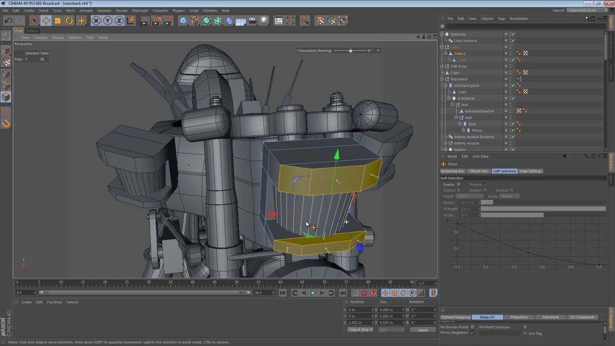
The eyes of the Razorback are going to be comprised of a combination of LIDAR (Light Detection And Ranging [basically a type of 3D scanning]) and FLIR (Forward looking infrared). This instrument array is pretty ad-hoc as the novel doesn’t talk too much about the look of them.
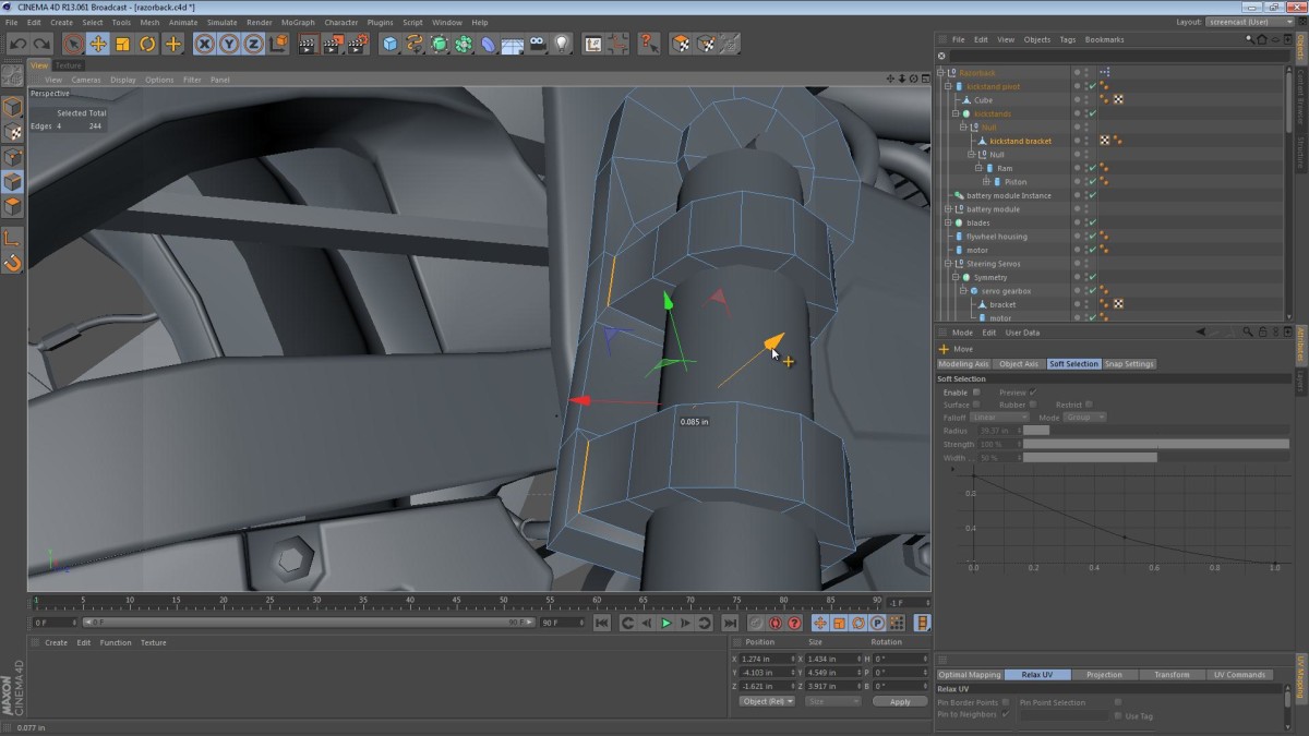
This video is a bit longer than the others (sorry), but there’s some good modeling technique in there. We look at creating the brackets/cradles for the hydraulic rams of the Razorback. Before getting into that heavy modeling, we look at the approach I settled on for pivoting them into and out of position.
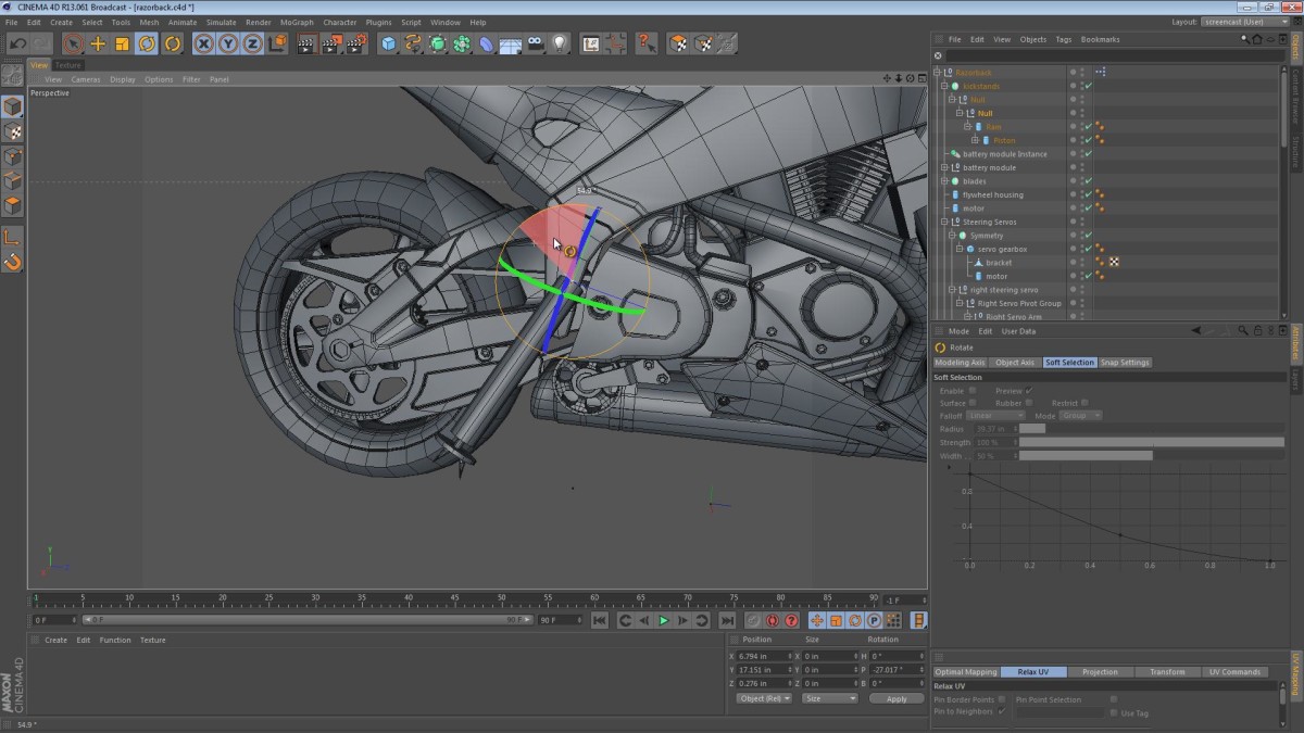
In this video we cover the modeling of the brackets that connect the steering servo gearboxes to the frame. While modeling the brackets, we get to use the Bridge tool to patch up geometry and focus on the benefits of using quads instead of triangles.
We also take a look at the kickstand placement taking issues such as ground clearance and style into account.
